1) Charge and pd relationship for two parallel conducting plates
If we place two conducting plates close together and deposit a charge on one then an equal but opposite charge appears on the inside face of the other. If we then investigate the pd across the plates as for different magnitudes of charge then we find both quantities are in direct proportion. This is illustrated below. This phenomenon introduces us to the concept of capacitance and we say the parallel plates have a capacity for storing charge. This will become clearer when we consider capacitors as components in circuits, ie circuit elements.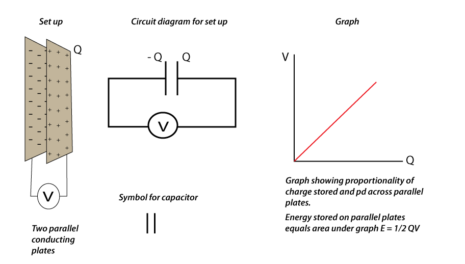
2) Investigating pd and charge for capacitors in circuits.
The following circuit is used to investigate the pd applied to a capacitor and the charge stored on one of its plates. A table and graph is shown. The pd is varied using the potentiometer in 0.2 V steps. when the switch is in position 1 the capacitor charges, in position 2 the capacitor discharges through the Coulombmeter and the reading is displayed.
3) Capacitance defined.
From the above activity we can see the gradient of the line is equal to Q/V = 1.0 mF. This means for every p.d of 1.0 V applied to a 1.0 m F capacitor, the capacitor will store 1.0 mC of charge and we write C = Q/V. The units of capacitance are CV-1 and we say 1 CV-1 = 1 F (remember in this statement C is for Coulombs). Circuit capacitors have capacitances much less than 1 F and tend to be stated in mF or mF. From this discussion it should be clear that the capacitance of a capacitor is equal to the ratio of charge to p.d.4) Problems using C = Q/V.
The following problem is typical of the question you might get using C = Q/V.A circuit capacitor has a capacitance of 2000 mF and a maximum working voltage of 15 V. This means if the voltage applied to the capacitor exceeds 15 V then it is likely the capacitor will be damaged. The following questions could now be asked
i) Calulate the maximum charge this capacitor can hold if it is not to be overloaded. Answer: Q = C V = 2000 mF x 15 V = 30 000 mC.
ii) If the capacitor is connected into an ac supply, then what is the maximum Vrms that can be used if the capacitor is not to be overloaded?
Answer: The peak voltage of the ac supply must not exceed 15 V, therfore Vrms = Vpk ⁄ √ 2 = 15 V ⁄ √ 2 = 10.6 V.
5) Energy matters and capacitance
Whenever two negative charges are pushed together their natural repulsion for each other must be overcome. Thus the force pushing them together does work and the work done is equal to the gain in electric potential energy of the two charges. This is precisely what is happening when charge builds up on a capacitor.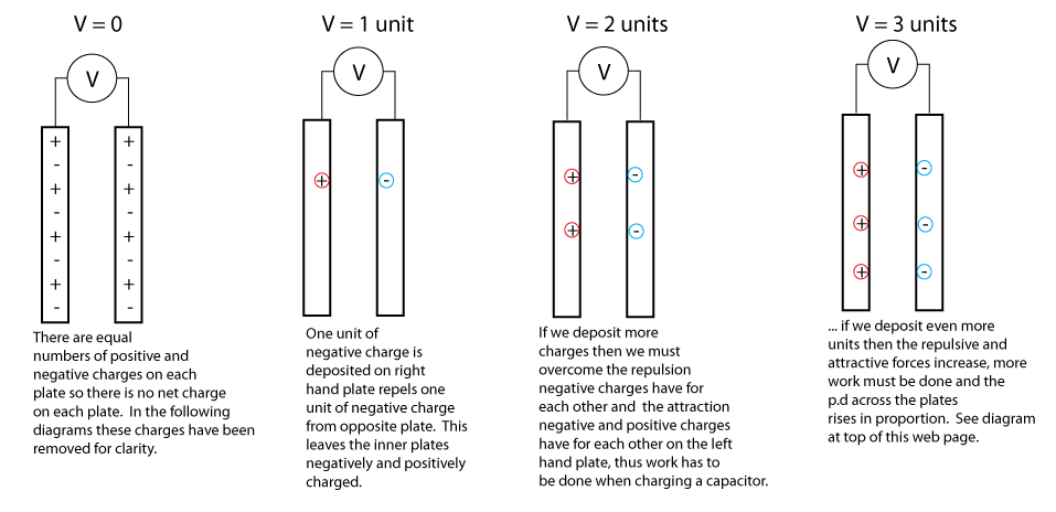
6) Work done and Q-V graphs
When a source of energy (cell or manual effort) deposits charge on a capacitor work needs to be done (energy expended) and this energy is stored between the capacitor's plate as electrical potential energy of the charges on its plates. Since the pd (energy per coulomb) between the plates rises in direct proportion to the charge deposited, we can draw the following graph. It should be clear that the area under this graph is the total energy needed to charge the capacitor and therefore the total energy stored between its plates, by virtue of the charge deposited there,
7) Investigating current and voltage in dc circuits containing capacitors
Now we have established some properties of capacitors it is appropriate to investigate current and voltage in RC circuits. An RC circuit is a circuit containing a capacitor and resistor in series. Firstly we will investigate RC circuits with dc supplies.1. Investigating current in an RC circuit.
A capacitor consists of two conducting plates that are insulated from each other. The insulation can either be air or some other material. Since no charges can flow through a capacitor we might expect the current in circuits containing capacitors might also be zero. We find this is not the case as the investigations show.
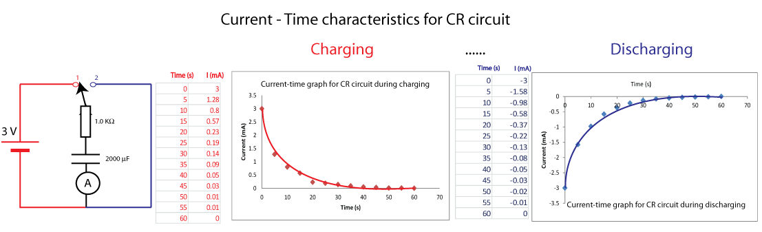
The image above is colour coded. Red represents the circuit, data and graph for matters involving charging the capacitor. Blue represents the circuit, data and graph for matters involving discharging the capacitor. Note the initial current in both cases is 3 mA, which is V/R nd the area under each graph is equal to the charge transferred to the capacitor during charging and the charge that leaves the capacitor during discharging.
2. Investigating voltage in an RC circuit (i) Charging.
Whenever a current flows in an RC circuit, charges build up on the capacitor thus raising the pd across its plates Vc, additionally the current flowing in the resistor means a pd exists across the ends of the resistor, VR. since we have a series circuit we can say;
Vcell = Vc + VR. This means if we know the current characteristic (graph) for a charging and discharging capacitor we can draw the voltage characteristics.
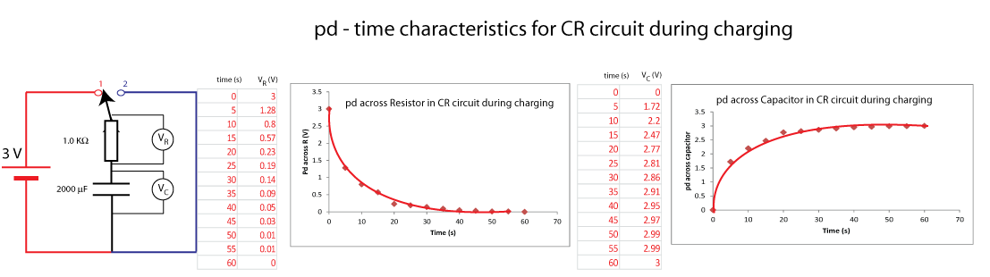
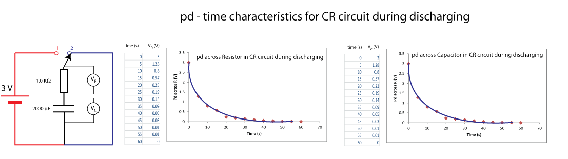
Note that the right hand columns of each table add up to 3.0 V. This is to be expected since Vcell = Vc + VR.
2. Investigating voltage in an RC circuit (ii) Discharging.
If we throw the switch to position 2, the capacitor will discharge through the resistor and the pd between its plates will fall. Note that during discharging the capacitor and resistor are in parallel. This means the pd across them will be equal and thus their pd discharging graphs are identical.
8) Problems on CR circuits when the supply is dc
These problems require you to understand the steps involved in finding the current and pd characteristic graphs for charging and discharging. The labelling of the graphs are required as well. Study the graphs above and try the following problem.Example
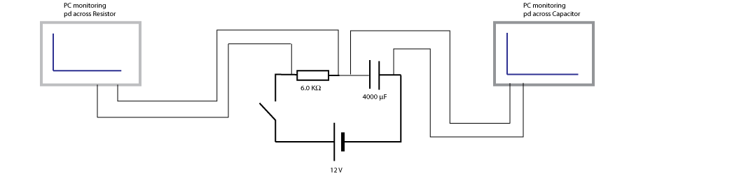
The pc terminals above monitor the pd across the capacitor and resistor when the switch is closed. If the capacitor takes 100.0s to completely charge...
i) Draw what will be seen on the pc monitors. Numerical values on axes are required for a full answer.
ii) Draw the current-time graph for the circuit. Numerical values on axes are required for a full answer.
iii) How much charge is stored on the capacitor when fully charged.
iv) How much energy is stored on the capacitor when it is fully charged.
9) Capacitors in ac circuits
Up to now we have discussed capacitors in dc circuits. If we connect a capacitor into an ac source the natural thing to investigate is current in the circuit and the frequency of the source. The circuit below enables us to do this and the result of the activity is shown on the graph.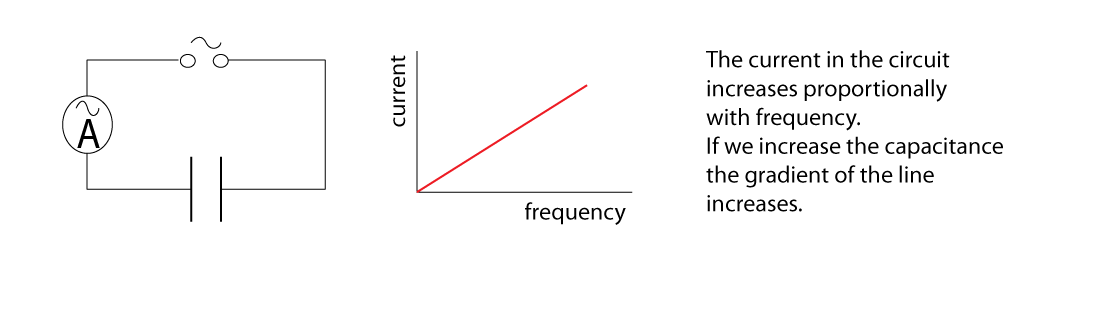
The fact that current increases with frequency is a useful fact to engineers when they are designing electronic circuits.
10) Uses of capacitors
Modern electronics would not be possible without capacitors. You are invited to find out the following.1. Why are capacitors are needed in flash lights for cameras.
2. What property of capacitors allow it to block dc signals but pass ac signals
3. Modern electronic circuits work with dc signals, but they are connected in the ac mains supply. Find out what rectification means and then find out what smoothing means. Find out how capacitors smooth a rectified signal.